
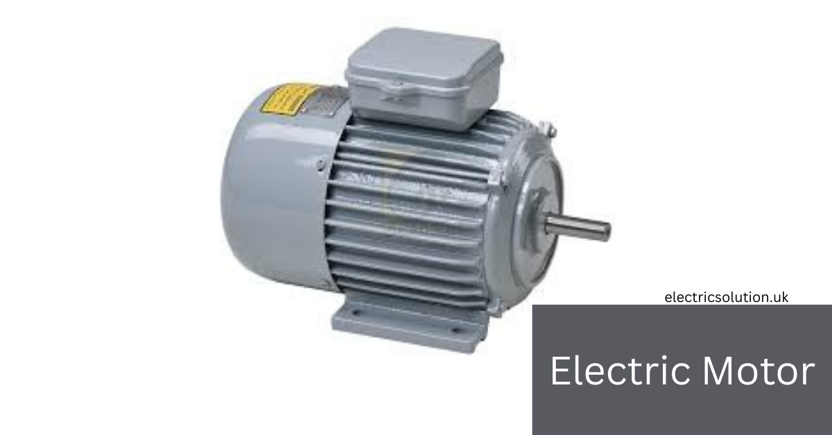
A machine that converts electrical energy into mechanical energy by electromagnetic phenomena is known as an Electric Motor. Motors usually work with the electric current available in the cables and interact with magnetic fields to create a force known as Torque on the shaft of the motors. The motors can be run by connecting them to a direct source such as rectifiers and batteries and also by alternating current sources such as inverters, generators, and power grids.
A motor is classified on the basis of its construction and uses, creating movements and shapes such as axial and non-axial. Motor types may be based on brushes or non-brushes, such as single-phase, two-phase, or three-phase electricity. Motors can create movements that are straight, linear, or circular, meaning rotary. When it is moving continuously, then it makes a device that causes sinusoidal that is creating very short movements.
A standard motor is used in industries and factories. The bigger motors, which can create 100 megawatts, are used in power ships, water storage systems, and pipelines. Motors are also used in home appliances, pumps, fans, machines, vehicles, computer hard drives, and watches.
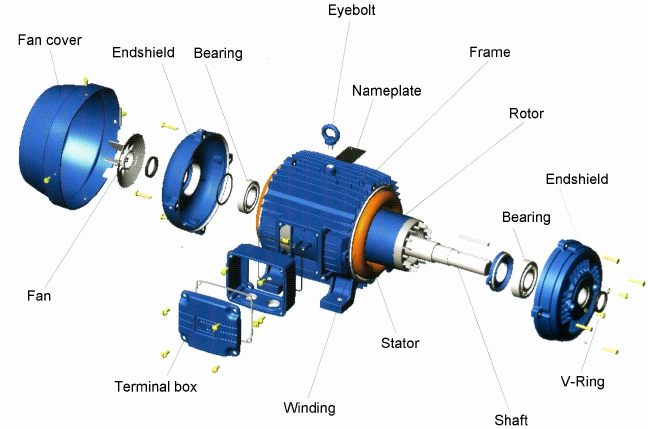
Components of electric motors
The Electric motor has two main components: the Rotor (moveable) and the Stator (not moveable). It has two parts: one is the field magnet, which is connected to the rotor, while the other part is the armature, which is attached to the stator. Both work together to form a magnetic circuit. Let’s discuss this.
1. Rotor
The name suggests that this is a moving part of the electric motor that delivers electric power. It holds conductors that carry currents on the magnetic field, which the stator exerts force on to turn the shaft.
2. Stator
It holds the magnetic field and surrounds the rotor. Either electromagnetic or permanent magnetic fields are responsible for the stator. Many thin metal sheets form the stator that are insulated from each other, called laminations. Laminations are made of electrical steel. It has a specified magnetic permeability, saturation, and hysteresis.
It has a great benefit because it reduces losses that result from induced circulating eddy currents. Mains-powered AC motors usually stop the wires inside from moving by covering them with varnish in a vacuum. This stops the wires’ windings from vibrating against each other, which may cause harm to the wire insulation. Resin-packed motors are used in deep machines, like washing machines, ACs (Air Conditioners), etc.
3. Gaps
There is a gap between the stator and the rotor because it allows it to run properly. The gap affects the electrical characteristics because small gaps help them to run effectively, while large gaps weaken the performance. Too small gaps affect the performance because small gaps cause friction and noise.
4. Armature
The armature has wire coils wrapped around a metal core that can be magnetized. When electricity flows through the wires, a magnetic field pushes on them (this is called the Lorentz force), which makes the rotor spin. Coiled wires are wrapped around the soft ferromagnetic core. It forms magnetic poles when energized with a current.
The Electric machines have two configurations: salient and non-salient pole configurations. Silent pole motors have projections in the rotor and stator ferromagnetic core that are known as poles facing each other. In this motor, the wires are wound around each pole. In the non-silent pole motor, the ferromagnetic core is in the form of a smooth cylinder. The windings are distributed evenly in slots around the circumference.
5. Commutator
It is a rotary switch that passes current to the rotor in the Electric Motor. In the rotor windings, it the current periodically reverses as a shaft rotates. It is in the form of a cylinder, which is composed of several metal pieces on the armature. Electrical contact brushes composed of soft conductive material press against the commutator. As the rotor spins, the brushes slide over different parts of the commutator, sending an electric current to the rotor.
The commutator changes the direction of the current every half-turn, so the force (torque) keeps pushing the rotor in the same direction. Without this, the rotor would stop because the force would keep changing direction. Today, most of these motors have been replaced by brushless, permanent magnet, and induction motors.
6. Shaft
The shaft of the motor stands out of the motor and connects to the machine where it satisfies the load. Since the force from the load is applied beyond the outer bearing, it is called an “overhung load.”
7. Bearings
The bearings allow the rotor to turn on its axis because they transfer the force of the axial and radial loads from the shaft to the motor housing.
Working of electric Motors
A force will be produced due to the two magnetic fields produced by the electric current, and the current is converted into mechanical energy.
Force and torque
According to the Lorentz Force Law, a magnetic field is perpendicular to the force between a current I in a conductor having length l.
F = IL X B Cross product
Tensor notation is used to calculate force in the motors.
Power of Electric Motor
The output power of the motor is given as
Pem = Tw = Fv
Where
T is the Torque
W is the angular Speed of the shaft
V is the velocity
F is the force
The mechanical power of the motor, which is also known as the imperial unit, is given as
Pem = WrpmT/5252 horsepower
A relationship between air gap power and the motor speed in the induction motor is given as
Pairgap = Rr/s (I^2r)
Where
(I^2r) is the square of current induced in the motor
Rr is the rotor resistance
S is the motor slip used in providing the relative moment needed for the induction of current in the rotors.
Back Electromotive Force (Back emf)
When the rotating part (armature) of the universal motor or an electric motor moves in the magnetic field, it produces voltage in the winding that pushes against the power supply and is known as the Back EMF. When a spin moves faster, a stronger emf will be produced, and the total voltage of the brushes must be equal to the back electromotive force plus voltage losses in the brushes and internal resistance so that the motor can control its speed.
When a motor has to work harder, then it slows down and generates very low back EMF, and the current will move, which helps the motor in handling the load.
Losses
Losses in the electric motor are due to the following reasons:
- Core losses
- Mechanical losses
- Resistive losses
- Aerodynamic losses
- Mechanical commutators spark
- Electrical commutators
- Dissipation of heat
Efficiency of the Electric Motor
The efficiency of the motor is given as
n = Pm/Pe
Where
N is the efficiency of the power
Pe = electrical input power = IV
Pm = mechanical input power = Tw
The efficiency of the motor is from 15% to 20% for the shaded pole and 98% for the permanent magnetic motor.
Goodness factors
G = w/resistance x reluctance
Types of Electric Motors
Types of motors are given below
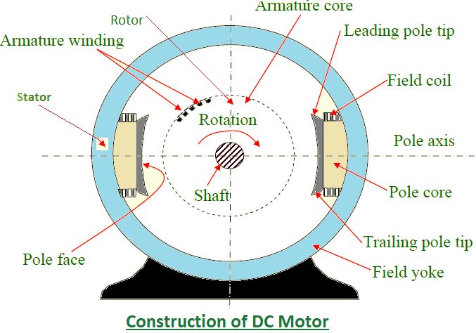
1. DC Motor (Direct Current Motor)
The first commutator Direct current motor was introduced by the English scientist William Sturgeon in 1832. In 1837, Thomas Davenport and Emily Davenport showcased the commutator-type Direct current electric motor that creates 600 revolutions per minute. But these motors were so costly that they made them unsuccessful. After so many attempts, in 1835, a less rotating motor was introduced by the Russian scientist Moritz Von Jacobi with unbelievable mechanical output power.
In 1838, Jacobi improved its motor and enabled it to drive a boat with 14 people. The first ring armature, designed by Antonio Pacinotti, provides a smooth and steady current to the motor. The invention helped the scientist to make a motor with better performance, and Zenab Germany made a DC motor that was successful at the commercial level in 1871.
Siemens, in 1867, noticed that two electric machines, such as a generator and a motor. To resolve this issue, Gramme and Pacinato introduced a system of two motors with 2 kilometers of wire. Here, one motor works as a generator, and the other works as a motor.
Finally, Sprague introduced the trolley system in 1887-1888, and in 1892, an electric elevator system was introduced by the Virigana and Richedman. The invention of DC motors has changed the industries’ work and provided more efficiency and performance than ever.
Types of DC Motors
Two types of DC motors based on brushes are given below:
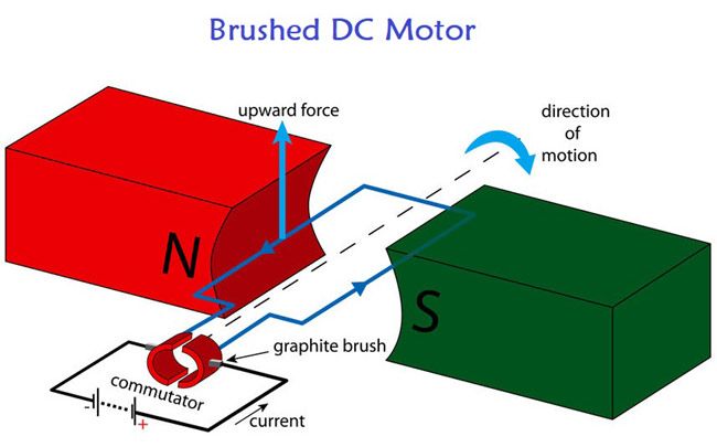
1. Brushed DC Motor
It had a commutator and brushes, making the motor inexpensive and simple. It had a commutator and brushes, making the motor inexpensive and simple. It is working on the Lorentz Principle, where current flows through the brushes and passes to the commutators. Brushed motors consist of a stator, which is a permanent or electromagnet creating a magnetic field. A rotor is here that is facing torque because current is passing through it. Brushes made up of carbon or graphite and conducting current through commutator.
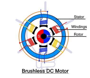
2. Unbrushed DC Motor
An electronic controller is needed to make it durable and efficient. An electronic controller is needed to make it durable and efficient. It has electromagnetics with copper winding, having a stationary part and a permanent magnet with a spinning part. This type of DC Motor creates a rotating magnetic field that helps in spinning the rotor. It is widely used in electric bikes, RC vehicles, robotics, industrial machines, computer cooling fans, and drones.
2. AC Motor
A type of electric motor that runs on alternating current, such as power grids and outlets. In this motor, direct currents change regularly. An AC motor works on the electromagnetic induction principle and creates a rotating magnetic field due to the flow of electric current. This magnetic field turns the rotor of the motor, which is known as the spinning part.
Alternating current motors are used in industrial machines and home appliances such as fans, air conditioners, and washing machines. It is also used in printing and copy machines, pumps, and electric trains.
An AC motor is more reliable and durable, requiring low maintenance. It is more efficient and powerful; that is why it is easily connected to power grids.
Types of Alternative Current Motors
1. Induction Motors
These electric motors are known as asynchronous motors and are the most common type that is widely used. The rotor is not connected directly by the AC motors because the magnetic field is spinning the rotors. It is a durable and simple type that is used in home appliances such as fans.
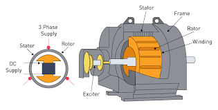
2. Synchronous Motor
The rotor is spun by the magnetic field that is induced due to the electric current and used at the same speed in robots and precision tools.